PCIe 12VHPWR and 12V-2x6 power connector issues

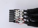
Huh, apparently the design guides for 12VHPWR connectors have been silently changed when relabeling to 12V-2x6, and you are now expected to have a metal bridge on both ends of the wire before going into the connector on either end...
It was the case with 12VHPWR as well. Not sure why people think that the wires are connecting to pins directly. They are being fused into one common rail inside the connector and this common rail is then connected to the pins.
Which also brings up an interesting question about the specs of the wires - is it provided by the plug spec or is it completely up to the cable maker to decide how many wires and with which characteristics should a cable has? I haven't looked this deep into the specs.

But it's seriously dangerous if they are bridged only on the PCB side and the bridge on the wire side of the connector is missing. Then you end up with the wires burning.
Exactly. Which is why the spec requires a bridge of all wires in the plug. So it is unclear how exactly these results from Der8auer even happen - they should only be possible if the bridge is missing or damaged.
 
There is also another factor.
Some plugs are rated for 30 mechanical "uses" (plug it in, remove it)
The high grade plugs are rated at 100 "uses".

So that adds another layer of complexity, due the the way the mechanical sides of plugs works.
If you keep unplugging and replugging, you add mechanical stress and suddenly the plug is worn and will have issues.
 
So it is unclear how exactly these results from Der8auer even happen - they should only be possible if the bridge is missing or damaged.
Completely missing. A quick search for available plugs for DIY 12VHPWR (not 12V-2x6) didn't give me any that explicitly guaranteed a common terminal inside the connector, and quite a lot that were obviously with individually inserted crimps and no electrical connection between them at all.

And as we know very well from the pictures of molten/falling apart 12VHPWR plugs from renowned power supply manufacturers, not bridging them was definitely the original design they followed for ATX 3.0 compatible power supplies. It was perfectly safe for the RTX 30 series.

So that means there is a lot of unsafe cables out there.
 
Last edited:
And as we know very well from the pictures of molten/falling apart 12VHPWR plugs from renowned power supply manufacturers, not bridging them was definitely the original design they followed for ATX 3.0 compatible power supplies.
Plugs were melting due to bad connection between the plug and the socket (i.e. user error when inserting the plug or some other reason due to which it has came out at some point), had nothing to do with the presence or absence of the bridge. Every 12VHPWR plug disassembly I've seen back in 2022 has shown the bridge in them so I'm pretty sure that this was the part of the original spec as well.
 
1739362483328.jpeg
So that's what they should look like on the inside. Everything is crimped or soldered into a single terminal.

S44178921fa02441cb85d462c96c1aec0s.jpg_960x960q75.jpg_.jpg
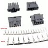
But you don't get that result with those plugs that are commonly sold for DIY. Those are all individual plugs and fully insulated from each other once inserted...

EDIT:
The first one is actually a custom design. The second one does unfortunately match the reference Molex design...
 
Last edited:
I'm also wondering if the sense pins have practical benefits.
I recommend this writeup from Anandtech.
Basically, as of PCIE 5.1 and the ATX 3.1 standard, the sense pins being unconnected means a PSU is not allowed to provide any power at all on the 12V pins.

This represents a major change from 12VHPWR to 12V-2X6, as unconnected used to allow 100W.

Combined with the sense pins now being further recessed while the 12V pins were brought forward, it should now be impossible for a GPU to request power start across a poorly connected 12V-2X6 cable.

So that's good but now we can return to uneven current flowing across the 6 different 12V lines. Would like to hear more about der8auer's setup.
 
So that's good but now we can return to uneven current flowing across the 6 different 12V lines.
It couldn't happen when using a conforming cable, because when measuring from either side of the cable, the resistance of each two pins on the same net (12V/GND) in the same connector would need to be less than <1 mOhm, and correspondingly also the total resistance of the whole cable less than effectively ~2 mOhm per meter.

If you find that the pins aren't connected, or the effective resistance measured between opposing ends exceeds the expectation, then it's bad news because the cable itself failed at balancing and will overheat. Those are far outside the specification.
 
Since I said I'd keep y'all updated
I bought one of these in March and it still hasn't caught fire
1739399820922.png
I believe the design of the cards is now different and 50 series dont need/cant use them
 
Spent all day testing various RTX 5090s, no luck reproducing the problem yet.
No shit. If you got an issue, then it's with the plug. Potentially the plugs on both ends of the specific cable. Not the socket on the GPU. Even though the GPU is absolutely to blame for ditching current balancing.

And the shorter the cable, the worse the issue gets. In fact, with a modded 20cm cable, you could get up to 14A on a single wire while not even exceeding the PCI-SIG specification on just how much (or little) the individual pins in the same connector area allowed to differ. So with cables shorter than 50cm per plug, the plugs must significantly outperform the specification in order to be safe to use.

The spec says the contact resistance may vary from 0 to 6 mOhm per pin, with the additional constraint that each pins resistance must not vary more than 50% from the average.

That already permits combinations where shorter cables will inevitably overload the wire without the connector being even the least out of spec.

Long cables are entirely safe. The permissible differences in connection resistance don't matter when completely dominated by the wire resistance, it's even somewhat self-balancing.


@DegustatoR those plugs with the built-in bridges... Those are all the custom made plugs used for the discontinued Cablemod adapters. The official Molex design for both 12V-2x6 and 12VHPWR have isolated pins.

Yes, that design with the common rail inside the plug is electrically superior, and avoids above issue entirely.

However, it suffered reputation damage thanks to the mechanical issues of 12VHPWR and it was exceptionally prone to triggering it due to the increased rigidness of the modified plug. It was not re-released with the 12W-2x6 thanks to that...


Right now, everything that says "12W-2x6" uses the Molex design. And with that design, only longer cables or plugs that outperform both relevant specifications are safe to use for 600W.
 
The official Molex design for both 12V-2x6 and 12VHPWR have isolated pins.
No, they don't. All these plugs are connecting the wires inside them.

images


This is the only way it could even function properly realistically. If some cables have plugs where wires are connecting to separate pins then this is a design flaw of these cables specifically.
 
No, they don't. All these plugs are connecting the wires inside them.

images


This is the only way it could even function properly realistically. If some cables have plugs where wires are connecting to separate pins then this is a design flaw of these cables specifically.
That is not a Minifit Molex plug. This is the relevant spec:

It even states explicitly the insulation between the terminals.

You got yet another picture of a ground down Cablemod custom 12VHPWR plug. Sadly that's not the used design for any 12V-2x6.
 
Last edited:
That's for the pins of the plug specifically, not for the internals of the plug or how the wires are connecting to the pins.
I've done some googling but I don't see anything which would suggest that there's even a specification on that - unless it is hidden somewhere in the PCI-SIG members only area.
Check point 6.3.1. There's the test that forbids an internal connection. It applies to any adjacent terminals with no wire attached.

That constraint isn't explicitly in PCI-SIG, and really makes no sense whatsoever with the pin assignment that PCI-SIG defines for the use in PCIe (noticed how this spec doesn't define terminals as 12V/GND?), but it's how the Molex connector is defined which PCI-SIG tells you to be compatible to.
 
That is not a Minifit Molex plug. This is the relevant spec:

It even states explicitly the insulation between the terminals.

You got yet another picture of a ground down Cablemod custom 12VHPWR plug. Sadly that's not the used design for any 12V-2x6.

That picture is actually from an older Igor's Lab article about Nvidia's own PCIE to 12VHPWR converter cables (i.e the ones that you'll find included in the box with GPUs).
Those cables apparently do have the 6 individual 12V wires soldered to a strip, so at least those are bridged as intended. There is still a point of contention in that the strip is described as thin and fragile.

The picture shows a cable that Igor commends for using crimped instead of merely soldered 12V wires. But at least they also look bridged to me.
I wonder how many cables out there implement the bridge concept correctly.
 
Last edited:
Back to der8auer's video: the original reporter used an Asus Loki 1000W, a PCIE 5.0/ATX 3.0 compatible PSU which sports a native 12VHPWR connector.
He connected it to the 5090 with a short 3rd party MODDIY 12VHPWR cable. I wonder if it is bridged or not?

For his own test, der8auer uses something completely different.
Here is a Corsair AX1600i PSU, which has Corsair Type 4 connectors on the PSU end, not a native 12VHPWR or 12V-2X6 connector. Notably, most Corsair PSUs do not yet use native connectors: Afaik only the 2024+ RMx series have these. My recently purchased HX1000i also does not use the native connector.
He connects it to the 5090 with what appears to be the official Corsair 'Premium Individually Sleeved 12+4pin PCIe Gen 5 12V-2x6 600W cable, Type 4, BLACK'. I can't find whether that is bridged either.
 
That picture is actually from an older Igor's Lab article about Nvidia's own PCIE to 12VHPWR converter cables (i.e the ones that you'll find included in the box with GPUs).
Context. Don't ignore the context. That image was posted as a negative example because it demonstrated exactly what Nvidia messed up in their very own 8-pin to 12VHPWR adapter when they were using a brittle, soldered connection without crimping. That one failed in a pretty unique way, where you could break the wires including the solder blob from the terminal because cold solder point, stiff wire due to solder creeping up the wire and far to brittle solder itself.

The picture shows a cable that Igor commends for using crimped instead of merely soldered 12V wires.
Unfortunately not. That text refers to the picture of a Molex style connector from a linked article.

I wonder how many cables out there implement the bridge concept correctly.
Me too. But you won't know unless someone decides to randomly dissect a working one. You can only tell that many are definitely Molex connectors when you can see each cable going individually into quadratic holes of a seamless nylon case. You know those are using disjointed terminals, because there's no other way to assemble them.
 
He connects it to the 5090 with what appears to be the official Corsair 'Premium Individually Sleeved 12+4pin PCIe Gen 5 12V-2x6 600W cable, Type 4, BLACK'. I can't find whether that is bridged either.
You can find high-res images of the plug on reddit when people ask if they have seated it correctly. You can clearly see the square receptacles for the individual terminals, and also that it has a seamless case. It does not have a bridge.
 
Back
Top