
You are using an out of date browser. It may not display this or other websites correctly.
You should upgrade or use an alternative browser.
You should upgrade or use an alternative browser.
Questions about PS2
- Thread starter Liandry
- Start date
Maybe I ask too much, but can anyone write or make pictureto show all PS2 graphics pipeline. Step by step. Thanks!

You care about the paths from the EE -> Main Mem -> VIF1 -> VU1 -> GIF -> GS
Note that those paths go through the VIF and the GIF (DMA chain processors). People don't talk about those processors much. To learn a bit about the VIF, go to http://www.vazgames.com/retro/PS2.htm starting at "Ten Things Nobody Told You About PS2" The GIF is similar, but simpler.
I have some new questions about PS2.
1) There is info that geometry calculations on VU1 didn't require main memory usage. But there's no some explanation about it. Can anyone tell more about it?
2) Did anyone know how much memory needed for one polygon? I mean then geometry goes from VU1 to GS those transfers use some part of bandwith between VU1 and GS. And I want to know how much.
3) There geometry data is stored on GS? In EDRAM?
Thank you!
VUs had small internal memories (a little bit like SPUs in Cell). IIRC VU0 = 8 KB and VU1 = 32 KB.1) There is info that geometry calculations on VU1 didn't require main memory usage. But there's no some explanation about it. Can anyone tell more about it?
Triangles have 3 vertices. But triangles can share vertices with neighbors (index buffer). Old hardware only supported 16 bit indices (so 2 bytes per index = 6 bytes per triangle). IIRC 16 byte vertex size was common. You commonly used uint16 positions (transform matrix had mesh scaling baked) and 16 bit vertex normals and 16 bit UVs. In total that is 3*2+3*2+2*2 = 16 bytes. Non-indexed triangle is thus 48 bytes. And indexed triangle is 6 bytes + separate vertex data (shared between many triangles). Commonly meshes have around 0.75 to 1.5 vertices per triangle (after duplicating UV/normal seams). So indexed triangle on average is around 24 bytes. But you don't usually transform triangles, you transform vertices (vertex shaders do the same). Index buffer data is often constant data (no need to modify it per frame).2) Did anyone know how much memory needed for one polygon?
Yes. And textures and render targets as well. You might need to swap them during the frame however, as the ESRAM is very small. I programmed our texture caching logic on PSP. Never programmed PS2 however, so I have never written VU code. PSP lacked VUs, but otherwise it was very close to PS2.3) There geometry data is stored on GS? In EDRAM?
Last edited:
Thank you for answers! But more questions.Triangles have 3 vertices. But triangles can share vertices with neighbors (index buffer). Old hardware only supported 16 bit indices (so 2 bytes per index = 6 bytes per triangle). IIRC 16 byte vertex size was common. You commonly used uint16 positions (transform matrix had mesh scaling baked) and 16 bit vertex normals and 16 bit UVs. In total that is 3*2+3*2+2*2 = 16 bytes. Non-indexed triangle is thus 48 bytes. And indexed triangle is 6 bytes + separate vertex data (shared between many triangles). Commonly meshes have around 0.75 to 1.5 vertices per triangle (after duplicating UV/normal seams). So indexed triangle on average is around 24 bytes. But you don't usually transform triangles, you transform vertices (vertex shaders do the same). Index buffer data is often constant data (no need to modify it per frame).
1) So if average polygon is 24 bytes and there is 100000 polygons per frame, then that will be ~ 2,28 MB of data per frame and is it's 30fps game that would be ~68 MB per second, right?
2) That means what from 1,2 GB/s bandwidth between VU1 and GS 68 MB will be used for geometry?
3) If it's 2,28 MB then it will take 2,28 MB of EDRAM memory every frame?
PS2 games used multipassing heavily. Same object was drawn multiple times (with blending). This is because there was no pixel shaders and the EDRAM offered high bandwidth for render targets. Multiple geometry passes = triangles read multiple times. 100K triangles sounds a bit too high for PS2 games (esp 60 fps games). Maybe some games achieved that, but it's hard to say how many triangles was the norm. As multipassing requires multiple geometry passes, games with more sophisticated "pixel shading" required more passes -> content needs to have less triangles.Thank you for answers! But more questions.
1) So if average polygon is 24 bytes and there is 100000 polygons per frame, then that will be ~ 2,28 MB of data per frame and is it's 30fps game that would be ~68 MB per second, right?
2) That means what from 1,2 GB/s bandwidth between VU1 and GS 68 MB will be used for geometry?
3) If it's 2,28 MB then it will take 2,28 MB of EDRAM memory every frame?
Reusing the same triangle multiple times of course costs more bandwidth, but it doesn't cost more memory. Unfortunately I don't remember our exact memory footprints, but I don't remember having any problems fitting meshes to EDRAM. Textures tend to take significantly more memory than meshes (both now and back then).
100K was just example.100K triangles sounds a bit too high for PS2 games (esp 60 fps games).
I just want to know EDRAM memory footprint. So this is why I asked if my calculations are right.Tell me please, there is frontbuffer, Z-buffer and textures in EDRAM. But you say there's also geometry. How does it stored? I mean how does it named? Is it part of framebuffer data?
And one more question. Is multipass rendering require geometry calculations for each pass. I mean calculation on VU1 or it just read/write operation in EDRAM?
PS2 games used multipassing heavily. Same object was drawn multiple times (with blending). This is because there was no pixel shaders and the EDRAM offered high bandwidth for render targets. Multiple geometry passes = triangles read multiple times. 100K triangles sounds a bit too high for PS2 games (esp 60 fps games). Maybe some games achieved that, but it's hard to say how many triangles was the norm. As multipassing requires multiple geometry passes, games with more sophisticated "pixel shading" required more passes -> content needs to have less triangles.
Reusing the same triangle multiple times of course costs more bandwidth, but it doesn't cost more memory. Unfortunately I don't remember our exact memory footprints, but I don't remember having any problems fitting meshes to EDRAM. Textures tend to take significantly more memory than meshes (both now and back then).
Would multipassing on PS2 necessarily require multiple geometry passes? For multi-texturing or other more complex shader arithmetic effects the VU1 program could just as well issue repeat GS primitive commands over a small batch of post-transformed geometry data cached in its data RAM, iterating between different states. GS state changes are cheap, especially since it can switch between two sets of them with no overhead.
I'm also skeptical that games would store geometry data in eDRAM given how precious of a resource it was. And I don't think this fits the available DMA modes, where you have:
Main RAM -> VIF1 (VU1 RAM, including some de-interleaving for geometry attributes)
Main RAM -> GIF (eDRAM for texture uploading)
In low level APIs, you give the hardware raw memory pointers. You manage the memory yourself. It is the same with any on-chip scratchpad memory. Simplest way is to hard code memory offsets for permanent resources (such as back buffer). And use a bump allocator for per level resources (reset allocator at the beginning of level load). Dynamic swapping of course needs something more complex. IIRC my allocator was a ring buffer style bump allocator. When it reached the end, it started from the beginning (evict as many resources that are needed to fit new in). It had some pseudo LRU logic (https://en.wikipedia.org/wiki/Cache_replacement_policies) to avoid evicting resources that were new or still required.Tell me please, there is frontbuffer, Z-buffer and textures in EDRAM. But you say there's also geometry. How does it stored? I mean how does it named? Is it part of framebuffer data?
That's 250k raw triangles per frame. Pretty nice. Multipassing of course means that content cannot have that many "actual" triangles. My experience is PSP based, so it is entirely possible that VUs helped PS2 push more triangles (in actual games). On PSP we used fp32 vertices for dynamic content (skinned characters). That obviously slows down the geometry pipeline compared to more compressed vertices. VUs could have helped with that.I think Jak and Daxter did over 100k per frame. I've even heard the sequels went as high as 15M per second.(I tried running pcsx2 in gpu perfstudio to confirm this, but couldn't get it to work) I don't think they held 60 fps all the time though.
VUs definitely make multipassing cheaper. Unfortunately my experience is from PSP, and it didn't have VUs at all. Multipassing inside VU would obviously reduce geometry read bandwidth requirement -> better keep meshes in main memory.Would multipassing on PS2 necessarily require multiple geometry passes? For multi-texturing or other more complex shader arithmetic effects the VU1 program could just as well issue repeat GS primitive commands over a small batch of post-transformed geometry data cached in its data RAM, iterating between different states. GS state changes are cheap, especially since it can switch between two sets of them with no overhead.
I'm also skeptical that games would store geometry data in eDRAM given how precious of a resource it was.
I programmed our texture caching logic on PSP.
Oh? What did you work on?
Warhammer 40,000: Squad CommandOh? What did you work on?
Two rendering programmers in the team, but we both did also other tasks beyond rendering (tools, game logic, network sync, etc). We had also full 3d terrain, but designers felt that it made game play less intuitive, so the terrain is mostly flat. Terrain materials, decals, shadows and tire tracks were rendered to a separate buffer and reused. Similarly to modern virtual textured terrain engines.
:smile2:I got that game on the X360. Didnt you help programming that version? Some guys I know are Warhammer geeks and I knew something about it from them, because they have photos of their mockups that they show in Warhammer conventions and stuff. But I am not into Warhammer and felt a bit lost, but enjoyed the orcs and stuff.Warhammer 40,000: Squad Command
Two rendering programmers in the team, but we both did also other tasks beyond rendering (tools, game logic, network sync, etc). We had also full 3d terrain, but designers felt that it made game play less intuitive, so the terrain is mostly flat. Terrain materials, decals, shadows and tire tracks were rendered to a separate buffer and reused. Similarly to modern virtual textured terrain engines.
Thank you! I'll read that info. But I meant something like this.
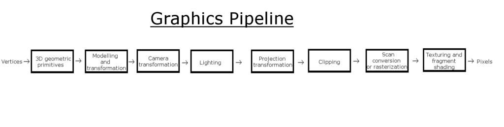
But for PS2. Maybe with info about what is dome by which block.
Rasterization and texturing was done by the GS. Everything else was done by VU1. The GS's EDRAM was for framebuffers, textures and texture palettes only. The GS did nothing regarding geometry. The only thing it knows how to do is to rasterize pre-transformed and clipped triangles and sprites.
When transforming vertices on the VU1, everything is done in software so it is very difficult but very flexible. We would use 16-bit integer components for positionX,Y,Z, normalX,Y,Z, and UV. You only need one 32-bit float scale-offset pair per-object per-channel to make this work. 2 bytes x 8 channels = 16 bytes per vertex. Indexing was done manually in software on the VU1 to make non-indexed triangle list/strips to be fed to the GS. I vaguely recall doing something like using 8 bit indices, but only working with batches of 128 verts in a batch. The 8th bit was used to indicate the end of a triangle strip. That way we could do "index + 111111110000000b & 100000000000000b" to shift the 8th bit up to bit 15 because that's where the GS wanted the end-of-strip indicator in some command. The VU didn't have bit shifting instructions.
Clipping was a manual and painful process on the VU1. It was very difficult to get right and even harder to make fast. It was pretty common to do a whole-batch vs screen bounding-box check in the hopes that you could prove the whole batch did not need to bother with clipping at all for that frame. That way you could have an alternate fast path that fed unclipped triangles to the GS with the assumption that none of them touch the edges of the screen.
Multipass very easy on PS2 because the GS could switch textures in just a few instructions. So, you could do a lot of work to transform and clip a small batch of triangles once, then send them to the GS multiple times with a different texture each time. Good thing it was easy, because each pass could only use one texture!
Thanks for the detailed info. VUs indeed are a perfect fit for the single texture GS + EDRAM architecture. Makes multipassing much more efficient.Rasterization and texturing was done by the GS. Everything else was done by VU1. The GS's EDRAM was for framebuffers, textures and texture palettes only. The GS did nothing regarding geometry. The only thing it knows how to do is to rasterize pre-transformed and clipped triangles and sprites.
When transforming vertices on the VU1, everything is done in software so it is very difficult but very flexible. We would use 16-bit integer components for positionX,Y,Z, normalX,Y,Z, and UV. You only need one 32-bit float scale-offset pair per-object per-channel to make this work. 2 bytes x 8 channels = 16 bytes per vertex. Indexing was done manually in software on the VU1 to make non-indexed triangle list/strips to be fed to the GS. I vaguely recall doing something like using 8 bit indices, but only working with batches of 128 verts in a batch. The 8th bit was used to indicate the end of a triangle strip. That way we could do "index + 111111110000000b & 100000000000000b" to shift the 8th bit up to bit 15 because that's where the GS wanted the end-of-strip indicator in some command. The VU didn't have bit shifting instructions.
Multipass very easy on PS2 because the GS could switch textures in just a few instructions. So, you could do a lot of work to transform and clip a small batch of triangles once, then send them to the GS multiple times with a different texture each time. Good thing it was easy, because each pass could only use one texture!
In contrast, PSP unfortunately didn't have VUs. It instead had a fixed function geometry transform engine that was closer to DX7 hardware T&L. IIRC it had max 4 hardware lights (vertex lighting) and up to 8 matrices (for matrix blending) and UV transform matrix as well. Pretty common stuff. GS only supported single texture (like PS2), no multitexturing. So if you wanted for example env maps (fake reflections), you had to multipass. But unlike PS2, this meant you have to transform the geometry twice.
PSP T&L pipeline had hardware clipping. Thank god. Unfortunately this means that I have never programmed a proper optimized clipping algorithm (my software rasterizers relied on huge guard band). Speaking of guard band clipping. A big guard band removes the need of most clipping operations. Since I didn't need to do manual clipping for GS, I don't know how big guard band it supported (range and precision of the post transform vertices). IIRC +-32768 (pixels) was common for early PC hardware.Clipping was a manual and painful process on the VU1. It was very difficult to get right and even harder to make fast. It was pretty common to do a whole-batch vs screen bounding-box check in the hopes that you could prove the whole batch did not need to bother with clipping at all for that frame. That way you could have an alternate fast path that fed unclipped triangles to the GS with the assumption that none of them touch the edges of the screen.
Last edited:
The thing I'm trying poorly to get across is that the VU didn't have a pre-set graphics pipeline in the style of DX7. It was a highly imbalanced general-purpose processor. You had a small amount of RAM, a few registers, some gimped 16-bit integer ops, some strong vector ops and a few odd ops to help pack and unpack data. Go design your own pipeline.
The rasterizer was fixed. So, it was kinda like writing your own software TnL for the Voodoo GPUs. Here's a C compiler. What's your pipeline? Except, you didn't get a C compiler. You got a funky assembly language to work with. All of the details I spoke of were what my team came up with. Other companies did things very differently.
That's why I posted the architecture diagram when asked for the pipeline diagram. The pipeline is:
The rasterizer was fixed. So, it was kinda like writing your own software TnL for the Voodoo GPUs. Here's a C compiler. What's your pipeline?
Except, you didn't get a C compiler. You got a funky assembly language to work with. All of the details I spoke of were what my team came up with. Other companies did things very differently.That's why I posted the architecture diagram when asked for the pipeline diagram. The pipeline is:
- The EE (CPU) sets up a command stream (buffer of bytes to be interpreted) for the VIF (DMA processor) to tell it to send and maybe shuffle some data from EE ram to VU1 ram. The EE then triggers the VIF command stream.
- The VIF moves data to the VU1. It can also trigger the VU to start executing from a specific instruction address.
- The VU runs whatever you coded up to generate a command stream for the GIF. You probably want to transform and light some verts somewhere in there if that's what you're in to But, the Sony engineers left that part up to you. The VU then triggers the GIF.
- The GIF DMAs data from VU ram to GS registers.
- Writing to GS registers triggers actions from the GS. Ex: when you write to the triangle corner position register the 3rd time (one location, 3 values stomping each other) you trigger a triangle to be rasterized according to parameters set up in other registers.
I believe everybody understood you. I just compared the fully customizable PS2 VU design to PSPs DX7 style T&L hardware. Both had similar pixel pipeline, but the geometry pipeline was completely different.The thing I'm trying poorly to get across is that the VU didn't have a pre-set graphics pipeline in the style of DX7. It was a highly imbalanced general-purpose processor. You had a small amount of RAM, a few registers, some gimped 16-bit integer ops, some strong vector ops and a few odd ops to help pack and unpack data. Go design your own pipeline.
Sometimes I wish modern GPUs would be programmed more like this. Fully programmable geometry pipelines, not just 1:1 vertex shaders. Of course in DX10/DX11 we've got many different shader types to extend the 1:1 VS functionality (GS, HS, HS patch function, DS). But all of these new shader types have limited uses and have various bottlenecks.That's why I posted the architecture diagram when asked for the pipeline diagram. The pipeline is:
The fun part was that all five of these steps could and should be happening in parallel. That was the pipeline.
- The EE (CPU) sets up a command stream (buffer of bytes to be interpreted) for the VIF (DMA processor) to tell it to send and maybe shuffle some data from EE ram to VU1 ram. The EE then triggers the VIF command stream.
- The VIF moves data to the VU1. It can also trigger the VU to start executing from a specific instruction address.
- The VU runs whatever you coded up to generate a command stream for the GIF. You probably want to transform and light some verts somewhere in there if that's what you're in to
- The GIF DMAs data from VU ram to GS registers.
- Writing to GS registers triggers actions from the GS. Ex: when you write to the triangle corner position register the 3rd time (one location, 3 values stomping each other) you trigger a triangle to be rasterized according to parameters set up in other registers.
Speaking of guard band clipping. A big guard band removes the need of most clipping operations. Since I didn't need to do manual clipping for GS, I don't know how big guard band it supported (range and precision of the post transform vertices). IIRC +-32768 (pixels) was common for early PC hardware.
From what I can find the input coordinate system is 0 to 4096 with 4 bits of fraction, so 16-bits total, for both X and Y. You can position this window to some offset in VRAM, plus there's a scissoring rectangle and you can change where the framebuffer is. So with proper offsets you can probably get some guardband in both axes, but not a lot.
I also don't know what the performance impact of the scissor rejection is, if anything. On PS1 you had to pay fillrate for every pixel that started outside of the viewport rectangle. It didn't do any attribute pre-multiplication to skip this and it would only stop early when rasterization exited the rectangle. But some triangles would be drawn bottom to top or even middle to top then middle to bottom, and this may have been done to avoid the Y clipping performance hit (although it was done to every triangle regardless of whether or not it was all inside the viewport, so there could have been other reasons)
Similar threads
- Replies
- 19
- Views
- 3K
- Replies
- 26
- Views
- 2K
- Replies
- 181
- Views
- 25K
- Replies
- 2
- Views
- 462